Lighting: In control
Nazzareno (Reno) Rossetti and Yin Wu from Maxim Integrated explain how a flexible LED controller can simplify automotive exterior lighting design
LEDs are becoming very popular in automotive exterior lighting, thanks to their superior lighting characteristics, efficiency and flexibility in design implementation. They can be used in a variety of light shapes and with different features.
The required multiplicity of LED configurations in automotive exterior lighting, combined with the variability of the car battery voltage, forces the use of a large number of integrated circuits, each tailored to a specific vehicle lighting function. A flexible controller IC can support many architectures and simplify automotive exterior lighting design.
Powering LEDs
LEDs have many automotive applications and are used in diverse arrangements from a single LED lamp to LED strings and matrices. Functions such as high beam, low beam, fog lights, daytime running lights (DRLs), and position and turn signal lights can all be implemented with LEDs.
Powered from a car battery, the input voltage is typically 12V but can be as high as 16V on a fully charged battery. Vehicles employing start-stop technology experience large voltage dips when the engine starts, so the lower limit for the power source can be well below the typical 12V, often 6V or even lower.
The switching regulators powering the LEDs must meet specific requirements. They must operate over the entire voltage range provided by the battery and be able to survive 60V dump voltage transients. The current amplitude must be very accurate, since it controls the LED colour.
For light dimming, time-slicing the LED current by using pulse-width modulation or PWM reduces the light’s brightness without affecting its colour. The PWM dimming frequency must be above 100Hz to be undetected as a flicker by the human eye.
A high and well-controlled PWM switching frequency above the AM frequency band is required to reduce radio frequency interference. Spread-spectrum modulation is also necessary to meet EMI standards. Finally, high efficiency helps reduce heat generation and improves system reliability.
Basic headlight
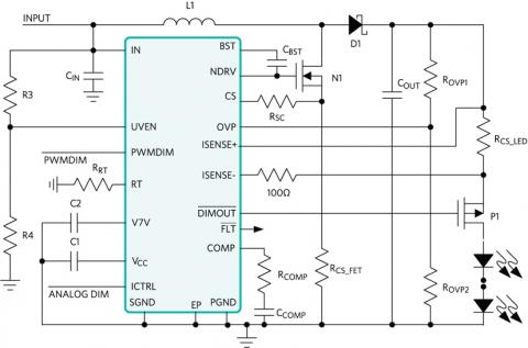
A basic headlight architecture that can accommodate a series of LEDs uses a boost converter. In a boost controller IC, one of the three feedback loops (current loop) ensures tight control of the output current. The other two feedback loops perform overvoltage protection (OVP loop) and overcurrent protection (OCP loop) for the string of 12 diodes, which develops 42V across the string (3.5V per LED).
In addition to current and voltage control, the IC must be equipped with all the features previously described – dimming, spread spectrum and so on. High-side current sensing via the resistors, Rx, is required to protect the LED system in case of shorts from the output to the ground or battery input.
Flexible architecture
Ideally, an LED controller should have a flexible architecture that supports multiple configurations that can implement different features. As well as the boost configuration, the buck-boost configuration should also be considered.
A buck-boost mode configuration is necessary if the diode string is short, for example two or three LEDs (7 or 10.5V), against a battery voltage that can vary from less than 6V (cold crank) up to 16V. If the concern is input-to-output isolation, then a single-ended primary inductance converter (sepic) for discontinuous output current or a chuck (continuous output current) converter may be the right device.
A single controller that supports many architectures, such as the one in the diagram, has clear advantages of economies of scale and ease of reuse. It can drive LEDs, allowing boost, high-side buck, sepic mode or buck-boost mode configurations. The device can be a single-channel high-brightness LED (HB LED) controller for automotive front-lighting applications such as high beam, low beam, daylight running lights, turn-signal indicators and fog lights.
Low EMI and noise
A 200kHz to 2.2MHz programmable switching frequency can allow the device to operate well outside the AM radio frequency band, avoiding interference with the automotive radio signal. Built-in spread-spectrum modulation also improves electromagnetic compatibility performance.
Spread-spectrum dithering added to the oscillator can alleviate EMI problems in the LED controller. The boost converter oscillator (RT pin in the diagram) can be synchronised to the positive-going edge of the PWM dimming pulse (PWMDIM). This means that the NDRV pulse goes high at the same time as the positive-going pulse on PWMDIM.
Synchronising the RT oscillator to the PWMDIM pulse guarantees that the switching-frequency variation over a period of a PWMDIM pulse is the same from one PWMDIM pulse to the next. This prevents flickering during PWM dimming when spread spectrum is added to the RT oscillator.
Conclusion
An LED controller can support a high number of architectures for automotive exterior lighting and greatly simplifies the design. The flexible design options use boost, high-side buck, sepic mode or buck-boost mode configurations, providing clear advantages in economies of scale and ease of reuse. In addition, a high switching frequency allows operation above the AM radio frequency band while built-in spread-spectrum modulation can reduce electromagnetic interference.
Nazzareno (Reno) Rossetti is an analogue and power management professional and Yin Wu a semiconductor business professional, both at Maxim Integrated