Powertrains put to the test
Hafeez Najumudeen and Kelvin Hagebeuk explore testing for the powertrains of electric vehicles
The powertrain lies at the heart of any hybrid or electric vehicle, and its development needs an understanding of the relationship and interactions between a combination of constantly varying electrical signals and physical parameters related to mechanical performance. To achieve this understanding, a variety of measurements have to be carried out as part of a complete test cycle.
This process involves the electrical signals in the power electronics systems linked to the high-voltage battery and inverter, along with the physical parameters involved in the process of electrical to mechanical conversion. To obtain a total understanding of the overall system performance, these measurements are typically linked with data from the powertrain management system transmitted over a vehicle serial bus network such as Can. Moreover, these electrical and mechanical tests have to be carried out simultaneously to arrive at an overall optimum, rather than optimising single components individually.
With today’s increased incorporation of power electronics and switching devices in overall system design, there is a growing need for accurate measurement of both the power behaviour of the applied power electronics and other inter-related electrical and physical parameters.
To establish the types of measuring equipment that are required for testing power electronics systems, it is useful to look at the various stages in the development of a power electronics product, which can be summarised as:
• architecture and design;
• verification and prototyping; and
• efficiency validation.
Architecture and design
At the architecture and design stage, the important areas to consider in the test process are that the system consists of a number of individual parts and includes characteristics such as fast inverter switching, high-frequency dynamic behaviour, overshoot on pulses, and the need to trigger on individual waveforms. Measurements of this type require an oscilloscope: ideally a mixed-signal instrument with multiple channels (eight is an ideal number to view input and output signals in three-phase systems).
The oscilloscope provides automated measurement of power parameters of voltage and current waveforms. These values can then be statistically processed and calculated to give peak, average and root-mean-square values, along with many other parameters such as power factor and q factor.
With a waveform-displaying product such as an oscilloscope it can seem easier to understand power measurement as even standard measuring features can be used to derive the value of active power. However, the accuracy and repeatability of the measurement is very difficult to quantify. Perhaps 5 to 10% accuracy is achievable without daily calibration, which could be very useful at an early stage of product development when it is not necessary to be able to measure very small improvements in the power efficiency of circuits or to present results that need to comply with a standard.
Verification and prototyping
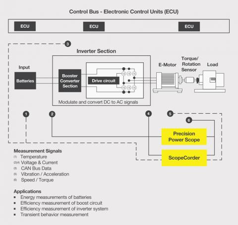
The next stage is verification and prototyping. The picture shows the same drive system with a number of additional parameters and measurement points that are necessary to gain a deeper insight into the overall application and the interactions that can occur between the various electrical, mechanical and physical parameters involved. These might include inputs from rotary encoders, sensor outputs that require signal processing or linearisation, and derived electrical units such as real power, energy used or RMS values. A deeper insight into an application requires the measurement and analysis of a combination of electrical, mechanical and physical signals and, in automotive applications, signals from buses such as Can and Lin.
These results then have to be processed with various calculations being carried out to produce trend displays, which in turn need to be combined into a single measurement overview from which it will become possible to find relationships and interactions between different parts of the drive system acting alongside one another. For this type of measurement, providing a unique insight into the dynamic behaviour of a system, engineers are looking for instruments combining the features of an oscilloscope and a data-acquisition recorder.
Such instruments are known as scopecorders, which can be used to measure and analyse a wealth of signals in real time and thereby speed up development and fault finding. As a portable data acquisition recorder, it can capture and analyse both transient events and trends for long periods. Using flexible modular inputs they can combine measurements of electrical signals, physical parameters from sensors and Can and Lin serial buses, and can trigger on electrical power related and other calculations in real time.
By combining electrical and physical measurements with Can or Lin bus data transmitted by the powertrain management system, they provide a thorough insight into the dynamic behaviour and the efficiency of the electromechanical system. The result is a considerable saving of time compared with other approaches such as analysis on a PC or the use of other software, enabling R&D engineers to identify the correlation between communications data transmitted over the vehicle bus and analogue data such as voltage, temperature and sensor signals, or the ECU’s control logic signals.
Efficiency validation
The final stage is efficiency validation. For this stage, the key factors that need to be tested are power analysis, conversion efficiency, harmonics, and the battery charge and discharge process. For tests of this type, the instrument of choice is the power analyser, offering high precision, high accuracy, high stability, and the ability to carry out calibrated measurements. Instruments of this type can perform efficiency tests by measuring the inputs and outputs of products such as inverters.
They can also accurately measure highly distorted voltage or current waveforms with high harmonic content up to the 500th order of the fundamental frequency: something that is especially important for measurements on new power conversion and power electronics devices. Using a dual harmonic measurement function makes it possible to measure simultaneously the harmonic content and perform harmonic analysis on two different sources, such as the input and output of an inverter or a variable-speed motor drive. The normal power parameters and harmonic data are measured simultaneously, providing for faster and more accurate power analysis.
For reliable and repeatable power measurements it is therefore vital to consider not only the accuracy of the reading, based on the results of a calibration performed at one time on one day, but also the stability and the precision of the instrument. Will the meter provide repeatable results six months or one year after the calibration? For example, the current input shunts, which convert current into voltage which can be sampled by the meter, need to be highly stable over all the current ranges to enable consistent measurements to be made under all values of input current and at the rated frequencies.
Hybrid instruments
In addition to the dedicated instruments described above, engineers and R&D professionals are also looking for hybrid instruments that can be used at all stages of the development cycle. When the power consumed by the load varies – for example during the start-up of a motor – it may be necessary to measure power at much shorter intervals. A specific requirement is for a versatile instrument to provide the time-based measurement functionality of an oscilloscope combined with the accuracy of a power analyser. Instruments such as precision power scopes provide users with flexibility, accuracy and wide bandwidth, allowing them to draw together the range of power readings needed to optimise the efficiency of boost circuits and inverters – two key elements in overall electric vehicle performance.
Like a power meter, a precision power scope is capable of accurately measuring steady-state power and related variables, since they share the same input techniques and measurement principles. However, as it also shares characteristics of oscilloscopes and scopecorders, it is capable of capturing and measuring the power arbitrarily over any part of the power waveform using start and stop cursors. This is particularly useful for examining transient phenomena and in the design of periodically controlled equipment. The trigger functionality helps set various trigger conditions based on the analysis of the transient phenomena to understand the behaviour of the system under test. Also, it offers the ability to analyse cycle-by-cycle trends and high precision harmonics, making it suitable for the measurement of transient effects.
During the start-up phase of an inverter and motor in an electric or hybrid car, for example, current increases can be analysed in each cycle. And, when the load changes rapidly, the engineers can gain insights that will enable them to improve the control of the inverter.
Conclusion
Electric vehicles, whether hybrid-electric or all-electric, present a complex series of challenges at all stages of the development process. This calls for the use of new classes of test instrument which, while based on familiar units such as oscilloscopes, recorders and power meters, introduce new combinations of features which make them particularly suited to these challenges.
Hafeez Najumudeen and Kelvin Hagebeuk are both product marketing managers at Yokogawa