Driving lights
Mark Scholten, senior FAE at On Semiconductor, considers the options for driving automotive LEDs
LED lighting is becoming more and more a part of our everyday life. From Christmas lights, to flat panel TVs, to the new billboard signs, and even replacing the incandescent light bulb. This effect is also being seen in the automotive industry.
One of the first applications that saw the incandescent bulb replaced by LEDs was the centre high mount stop lamp (CHMSL), also known as the third brake light. Shortly afterwards, many of the tail lights had gone to LED. Then other applications followed from indicator backlighting on buttons, daytime running lights (DRLs), dome lights, instrument cluster backlighting, and finally even the headlamps started changing over from HID bulbs to LEDs.
The question for a designer is how to drive these devices efficiently and cost effectively to maintain their high reliability, especially in automotive environments that are typically quite challenging.
Lowest cost
LEDs are different from incandescent bulbs in that they want to be driven by a constant current. The simplest way to drive an LED is with a resistor; this works fine if the voltage is regulated, such as in a 5V rail, because then the current going through the LED is simply the supply voltage minus the forward drop of the LED, divided by the resistor value, which ends up being a fairly constant current. But if the need is to run off the vehicle’s battery supply, the voltage can vary from as low as 4.5V for a start-stop system right up to 19V. And this doesn’t include the double battery jump start test at 24V for two minutes.
One solution to this problem that engineers have used with varying battery voltages is to measure this voltage and then pulse-width modulate (PWM) the LED current to keep the average current the same. This can work, but the peak current will increase at higher input voltages, so care must be taken not to exceed the maximum current rating of the LED. One must also make sure that during the peak current pulses the LED’s maximum junction temperature is not exceeded. If temperature or current ratings are exceeded then component reliability and lifetime will be reduced.
Another thing to consider is how to deal with the passenger compartment lighting, as many of the LEDs need to be controlled by the driver’s side dimming control. The dimming function also uses PWM control of the lights. But if one is already PWMing the LEDs for variations in battery voltage, then another layer of PWMing is needed on top of this for the driver’s dimming function, which can make things a bit more challenging for the software engineer.
Next best
The next best answer is to use a constant current regulator (CCR). These are two-terminal devices that keep the current constant through the LED, no matter what the battery voltage. These devices can be used anywhere in the LED string, since they are a floating regulator and can act as a current source or sink. This makes the driver’s side dimming function much simpler to implement.
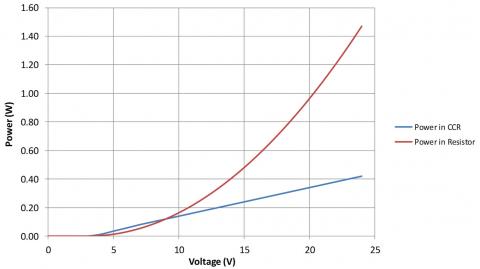
One of the advantages of using a constant current driver over a resistor is that the power goes up linearly at higher input voltages, as opposed to a resistor in which the power goes up via a squared function.
For example, most vehicles require a minimum LED brightness level at a 9V battery input. And let’s say that for this brightness level 20mA of current is needed through the LED. And let’s assume that the LED has a voltage drop of 3V. Then a resistor of 300Ω {(9V - 3V)/20mA} is needed. But as the battery voltage increases, the power in the resistor goes up compared with a CCR. The effect is dramatic and is illustrated in the diagram.
Another advantage is that a CCR will also turn on faster than with a resistor-based method, so brighter LEDs can be achieved at lower input voltages, while keeping a constant brightness at higher input voltages.
To provide products for a wide range of applications, semiconductor manufacturers need to offer devices with various current ratings. Fixed current CCRs are available from 10 to 350mA. There are also several adjustable CCRs in the 35-70, 60-100, 90-160, and 150-350mA ranges.
High current LED drivers
The above two approaches are fine for lower current LEDs, but as soon as one gets to 100mA or more, then designers need to start looking at switching regulators, due to power dissipation issues. To drive a number of LEDs in a string, say for a LED headlamp or for backlighting a video display, a boost supply is typically used. When trying to drive just a couple of high brightness LEDs, for a dome lamp or a trunk lamp, a buck regulator is used.
In the boost application, when the mosfet switch is on, the LED current is provided by the output caps. When the fet switches off, the energy that was being stored in the inductor provides the output current.
For the buck application, the LED current is supplied by the output inductor. The current in the inductor ramps up when the switch is closed, and then ramps down when the switch opens. Because the inductor current is continuous it acts like a current source for the LEDs that are in series with it. The output capacitor can actually be removed in some instances, saving circuit cost.
The pro to using switching regulators is that they are very efficient, so less power is wasted as heat. The cons are that they are more complex, more costly, they can generate EMI, and take more design effort. But with a careful design, they can be a very reliable and efficient for driving high brightness LEDs.