Power Technologies: Two directions
Dual 48 and 12V battery automotive systems require bi-directional DC-DC controllers for optimum performance, says Bruce Haug, senior product marketing engineer at Analog Devices
With fuel economy regulations tightening and autonomous-driving capability with connectivity proliferating, the old-fashioned 12V automotive electrical system has reached its usable power limit. Furthermore, a vast increase in automotive electronic systems coupled with related demands on power have created an array of new engineering opportunities and challenges.
As a result, the 12V lead-acid battery automotive system with its 3kW power limit has been supplemented.
A newly proposed automotive standard, LV148, combines a secondary 48V bus with the existing 12V system. The 48V rail includes an integrated starter generator (ISG) or belt start generator, a 48V lithium-ion battery and a bi-directional DC-DC converter for delivery of up to 10kW of available energy from the 48 and 12V batteries combined. This technology is targeted at conventional internal combustion automobiles, as well as hybrid electric and mild hybrid vehicles, as car manufacturers strive to meet increasingly stringent CO2 emissions targets.
Typically, the 12V bus will continue to power the ignition, lighting, infotainment and audio systems. The 48V bus will supply active chassis systems, air conditioning compressors, adjustable suspensions, electric superchargers and turbos and support regenerative braking.
The decision to use an additional 48V bus, which is expected be available across production model ranges soon, can also support starting the engine, which would make stop-start operation smoother. Moreover, the higher voltage means smaller cable cross-sections are needed, which reduces cable size and weight.
Today's high-end vehicles can have more than 4km of wiring. Vehicles will become more like PCs, creating the potential for a host of plug-and-play devices. On average, commuters spend nine per cent of their day in an automobile. Thus, introducing multimedia and telematics into vehicles can potentially increase productivity as well as providing additional entertainment.
The key components for autonomous driving include a computer, cameras, radar and lidar sensors, all of which require additional energy. This additional energy is required to improve vehicles’ connectivity, not just to the internet, but to other vehicles and buildings, traffic signals and other structures in the environment. Furthermore, drivetrain components, power steering, oil and water pumps will switch over from mechanical to electrical power.
The future for the 48V battery system is much more near-term than the fully autonomous car, although many automotive suppliers see strong demand for the technological building blocks ultimately needed for self-driving vehicles over the next few years. According to some auto manufactures, a 48V based electrical system results in a 10 to 15 per cent gain in fuel economy for internal combustion engine vehicles, thereby reducing CO2 emissions.
Moreover, future vehicles that use a dual 48 and 12V system will allow engineers to integrate electrical booster technology that operates independently of the engine load, thereby helping improve acceleration performance. Already in its advanced development phase, the compressor is placed between the induction system and intercooler and uses 48V to spin-up the turbos.
Nevertheless, the implementation of an additional 48V supply network into vehicles translates into major design challenges for suppliers across the value chain. In particular, providers of semiconductors and electronic control units (ECUs) will be affected; they will need to adjust their operational range to the higher voltage and in part redesign their products.
Correspondingly, the manufactures of DC-DC converters will need to develop and introduce specialised ICs to enable this high power transfer. This has led to the design and development of a number of DC-DC converters that are able to facilitate this energy transfer with very high efficiency to conserve energy while also reducing the thermal design required due to their much lower power loss.
It is clear there is a need for a bi-directional step-down and step-up DC-DC converter that goes between the 12 and 48V batteries. This DC-DC converter can be used to charge either battery and allows both batteries to supply current to the same load if required. Most of the early 48 and 12V dual battery DC-DC converter designs use different power components to step-up and step-down the voltage. However, bi-directional DC-DC controllers can use the same external power components for the step-up conversion as they do for stepping down the voltage.
Single bi-directional IC
A 100 and 30V bi-directional two phase synchronous buck or boost controller can provide bi-directional DC-DC control and battery charging between the 12 and 48V board nets. It can operate in buck mode from the 48V bus to the 12V bus or in boost mode from 12 to 48V. Either mode can be configured on demand via an applied control signal.
Up to 12 phases can be paralleled and clocked out-of-phase to reduce input and output filtering requirements for applications up to 250A. A current-mode architecture can provide current matching between phases when paralleled. Up to 5kW could be supplied in buck or boost mode with a 12-phase design.
When starting the car, or when additional power is required, the converter can allow both batteries to supply energy simultaneously by converting energy from one board net to the other. Up to 97 per cent efficiency can be achieved and the on-chip current programming loop regulates the maximum current that can be delivered to the load in either direction. Four control loops, two for current and two for voltage, enable control of voltage and current on either the 48 or 12V board nets.
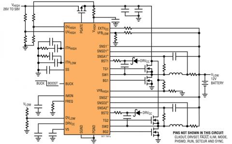
The diagram shows a typical applications schematic. The p-channel mosfet shown at the top of the schematic is for over current and short circuit protection.
Integrated start-generator
The electronically controlled ISG replaces both the conventional starter and alternator with a single electric device for the following reasons:
- • To eliminate the starter which is only a passive component during engine operation;
- • To replace the present belt and pulley coupling between the alternator and the crankshaft;
- • To provide fast control of the generator voltage during load dumps; and
- • To eliminate the slip rings and the brushes in some present wound rotor alternators.
The ISG has three important features, which are the start-stop function, electricity generation and power assistance. The ISG allows the internal combustion engine to turn off its motor to save fuel at stops and instantly re-starts upon pressing of the accelerator pedal.
Normally referred to as a start-stop system, an ISG makes for a smoother transition when starting the engine. As with a conventional alternator, the ISG produces electric power when the vehicle is running. In addition, the ISG can help to decelerate the vehicle by generating electric power (regenerative braking). The electric power generated during regenerative braking charges the 48V battery, which in turn reduces fuel consumption and its resultant CO2 emissions.
Buck and boost modes
A converter can be dynamically and seamlessly switched from buck mode to boost mode and vice versa via a simple control signal. There are two separate error amplifiers for Vhigh or Vlow regulation. Having two error amplifiers allows fine tuning of the loop compensation for the buck and boost modes independently to optimise transient response.
When the buck mode is selected, the corresponding error amplifier is enabled, and ITHlow voltage controls the peak inductor current, the other error amplifier being disabled. In boost mode, ITHhigh is enabled while ITHlow is disabled. During a buck to boost or a boost to buck transition, the internal soft-start is reset. Resetting soft-start and parking the ITH pin at the zero current level ensures a smooth transition to the newly selected mode.
Multiphase operation
Multiple converters can be daisy chained to run out of phase to provide more output current without increasing input and output voltage ripple. The sync pin allows the device to synchronise to the CLKout signal of another converter. The CLKout signal can be connected to the sync pin of the following device to line up both the frequency as well as the phase of the entire system. Up to 12 phases can be daisy chained to run simultaneously out of phase with respect to each other.
A demonstration circuit can be configured with two or four phases using one or two devices. The photo shows the four phase version and, when operating in buck mode, this demo circuit has an input voltage range of 30 to 75V and produces a 12V output at up to 60A. When operating in boost mode, the input voltage is from 10 to 13V and produces 48V at up to 10A.
The efficiency curves are representative of a four-phase demo board design using two devices. The buck mode curve steps the 48V down to 12V at up to 60A, while the boost curve steps up the 12V to 48V at up to 10A, both with 97 per cent peak efficiencies.
Over current protection
In buck mode, current fold-back protection can limit power dissipation in an over current condition or when the Vlow is shorted to ground. If the Vlow falls below 85 per cent of its nominal output level, then the maximum sense voltage is progressively lowered from its maximum programmed value to one-third of the maximum value. Foldback current limiting is enabled during soft-start. Under short-circuit conditions with very low duty cycles, it will begin cycle skipping to limit the short-circuit current.
In a typical boost controller, the synchronous diode or the body diode of the synchronous mosfet conducts current from the input to the output. As a result, an output (Vhigh) short will drag the input (Vlow) down without a blocking diode or mosfet to block the current.
An external low RDS(on) p-channel mosfet provides input short-circuit protection when Vhigh is shorted to ground. In normal operation, the p-channel mosfet is always on, with its gate-source voltage clamped to 15V maximum. When the UVhigh pin voltage goes below its 1.2V threshold, the fault pin goes low 125µs later. At this point, the Pgate pin turns off the external p-channel mosfet.
Conclusion
This type of converter can bring a new level of performance, control and simplification to 48 and 12V dual battery DC-DC automotive systems by allowing the same external power components to be used for step-down and step-up purposes. They operate on demand in buck mode from the 48V bus to the 12V bus or in boost mode from 12 to 48V.
Up to 12 phases can be paralleled for high power applications and, when starting the car or when additional power is required, they allow both batteries to supply energy simultaneously to the same load.
The additional 48V battery running a portion of a vehicle’s electrical system will play a central role in increasing available energy while reducing wiring harness weight and losses. This additional energy capacity paves the way for new technologies, enabling cars to be safer and more efficient, all while lowering CO2 emissions.
Bruce Haug is senior product marketing engineer at Analog Devices