Sensors: Right angles
Scott Milne from Allegro Microsystems discusses angle sensors in automotive electronic systems
As the use of electronics in the modern automobile becomes more ubiquitous, so the electronic devices and subsystems within the car are evolving to meet the changing demands of both the physical requirements of the automotive environment and the changes in the industry brought about by new commercial, environmental and regulatory pressures.
These pressures have led to an increased demand on electronics in safety critical systems, particularly in two key areas: redundancy and diagnostics. Redundancy provides increased safety by duplicating hardware components to keep systems operating in the event of failures in individual elements. This has led to many sensing devices now being produced in single and dual configurations, and to some safety-critical systems incorporating three of four individual sensors operating in redundant voting systems.
Diagnostic features, including advanced self-test functions that provide fault information to the electronic control unit, are assuming increasing importance in functions such as electronic power-assisted steering (EPS). Whereas in earlier generations of such systems where the EPS system was truly providing assistance, there were still mechanical linkages to fall back on in the event of failure, in modern drive-by-wire or autonomous vehicles this back-up is not available – hence the need for high-level self-testing of both digital functions and analogue signal paths.
The demand for these functions is reflected by the increasingly stringent regulatory environment in the automotive industry, and in particular the functional safety requirements specified in the Asil (automotive safety integrity level) standards adopted by the automotive industry worldwide.
The result is that sensing and control components for use in the automotive industry are becoming more sophisticated, with a high silicon content and more built-in functionality. This trend is already well established in the areas of speed sensing and motor control, and is now embracing the area of angle sensing.
Circular vertical Hall
Angle sensing has always been challenging, particularly in harsh automotive and industrial environments, where high temperatures, humidity, dust, dirt and oil are always present.
Consistent accuracy over extended temperature ranges, the need for precise measurement at higher speeds as well as enhanced system capabilities and Asil design features are all requirements in today’s demanding angle sensor applications.
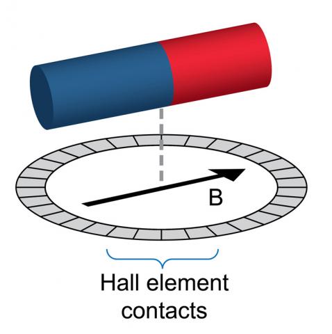
Angle sensors based on circular vertical Hall (CVH) technology (see diagram) provide a system-level angle sensor in a single IC, which, unlike some solid-state angle sensor ICs, does not require a concentrator and complex package assembly, thus providing lower system costs. CVH technology also enables fast refresh rates (for example, 25µs) and low angle accuracy errors (more than 1˚C over a -40 to +150˚C operating temperature range). Because of this high refresh rate, CVH based angle sensors can support target magnets rotating at very high speeds.
CVH technology is also a single-channel type of angle measurement system, which results in higher angle accuracy and reduced temperature drift performance. Unlike other angle sensor IC technologies that use a dual-channel sine-cosine method for producing an angle measurement, there are no channel-to-channel offsets that may result in accuracy errors.
CVH based angle sensors rely on comparing the phase of the target magnetic field relative to an internal reference signal, thereby making them immune to saturation issues that affect products that rely on the magnitude of the magnetic signal measured to calculate the angle. Also, since the CVH elements are not adversely affected by large magnetic fields and there is no concentrator required, CVH based angle sensors can be used with large target magnets (more than 900G), thus increasing the immunity to stray magnetic fields.
In a typical angle sensor, the CVH sensing element is integrated with back-end digital signal processing functions, eeprom for storing factory and customer programmable parameters, and on-board diagnostics, resulting in a system on chip. Also included are features such as linearisation and potentially a redundant die in a single package to enable the support of Asil requirements.
At the heart of the CVH circuit is an n-well ring or moat containing vertical metal contacts (64 in the example in the diagram) and their associated switching elements. Digital logic is used to step and configure groups of five contact elements repeatedly to generate effectively mini Hall elements. At each step or group configuration around the ring, a voltage is measured.
As the digital logic steps through the 64 contacts and switches, a voltage is measured at each of the steps, resulting in a sine wave that represents the orientation of the target magnet hovering above the angle sensor IC.
Stepping through all the contact elements in the ring is accomplished very rapidly: typically 25µs to step around the entire ring.
The resultant sine wave is passed through a bandpass filter and rectified into a square wave, which is then compared with a reference signal generated internally by the angle sensor IC, and the phase difference between the falling edges of these two signals represents the angle measurement of the target magnetic field suspended over the IC.
On-axis and off-axis
CVH technology based angle sensor ICs support two generic types of angle measurement systems: on-axis or end-of-shaft angle sensing; and off-axis or side-shaft angle sensing.
In on-axis systems, the angle sensor is centred directly under or over the rotating target magnet, while in off-axis systems it is positioned to the side of the rotating magnet. With these two types of angle measurement, numerous angle sensing applications can be supported.
On-axis angle sensing is the most common type of angular position measurement system, and yields higher accuracy results. It also requires less digital post-processing than off-axis angle sensing. It is typically used in electronic power steering, windscreen wiper, and transmission or clutch applications.
Off-axis angle sensing is not as ubiquitous as on-axis systems due to the inherent angle accuracy measurement challenges it presents. Nevertheless it can enable simpler mechanical designs and potentially lower system costs, which makes it attractive to system designers.
Off-axis angle sensing involves an angle sensor device that measures the angular position of a magnetic field generated by either a ring magnet that is attached around a shaft, or a puck magnet that is positioned adjacent to the angle sensor IC. As the shaft and ring magnet assembly or puck magnet turns, depending on the mechanical configuration, the angle sensor IC measures the resulting angle position of the rotating magnet.
One major issue with off-axis angle sensing is that a wide variation in magnetic field is observed by the angle sensor. As a result, the angle sensor requires significantly more digital post-processing of the raw angle measurement to achieve an accurate final angle measurement output. The additional post-processing, such as harmonic linearisation, adds cost and complexity to the angle sensor IC and increases the latency of the measurement to produce the same level of angle accuracy as an on-axis angle measurement system.
Flexible output
Angle sensors are increasingly moving to digital output protocols to increase noise immunity, but also to communicate all the diagnostic information described previously that is gathered on chip. There are multiple output formats the system designer can select, each of which offers various trade-offs. Serial interfaces (SPI) can run at clock rates up to 10MHz, greatly reducing the time needed to read and write to the part. This is particularly important for applications such as motor position sensors where the time to transmit the angle information can materially impact the control algorithm for the motor.
This comes, though, at the cost of requiring four pins, which drives BoM cost and weight. At the other end of the spectrum is the Sent single edge nibble protocol, a single wire system that helps reduce the cost and weight of wire harnesses that connect remote sensors to the ECU.
The downside of Sent historically is it is relatively slow compared with SPI and other protocols, and it does not support multiple ICs on the same bus.
As EPS system integrators continue to be challenged with satisfying competing requirements of increasing system-level safety ratings and at the same time decreasing overall BoM costs, it is increasingly important that they select the right partners to enable efficient and safe designs.
Scott Milne is product line director at Allegro Microsystems